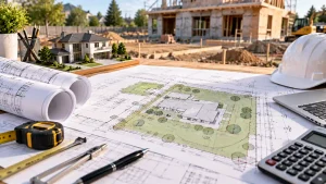

How to read a site plan is one of the most valuable skills for homeowners, contractors, and property owners preparing for a building permit. If you’ve never seen a professional site plan before, it may look like a confusing mix of lines, numbers, and symbols. However, once you understand the basic layout and key elements, reading a site plan becomes much easier.
A site plan shows how a building is positioned on a property, including property boundaries, setback lines, existing structures, driveways, utilities, and proposed construction. It is one of the most important documents required for a building permit application. In this guide, you’ll learn how to read a site plan step by step, understand every major symbol and measurement, and interpret it just like a city plan reviewer.
What Is a Site Plan?
A site plan is a scaled overhead drawing that shows the full layout of a property. It is used for building permits, zoning approvals, and construction planning. It typically includes:
- Property boundaries
- Existing and proposed structures
- Setback requirements
- Driveways, patios, and walkways
- Easements and utility lines
- North direction and scale
A site plan ensures your project complies with local building regulations before construction begins.
How to read a site plan: The Title Block
The title block is usually located in the bottom right corner of the site plan. It provides key project identification details that help permit reviewers verify the drawing. It typically includes:
- Property owner name and project address
- Project description (new build, addition, etc.)
- Drawing scale (e.g., 1” = 20’)
- North arrow orientation
- Drafter or design firm information
- Date and revision history
- Sheet number (if multiple pages exist)
This section is critical because incorrect information here can lead to permit delays or rejection.
Property Lines
When learning how to read a site plan, the first element to identify is the property lines. Property lines define the legal boundaries of your land and are typically shown as bold solid or dashed lines forming a closed perimeter. These boundaries determine where construction can legally take place and are one of the first things permit reviewers examine. Key details include:
- Exact boundary lengths (in feet or meters)
- Total land area (square footage or acreage)
- Corner points or survey markers
Understanding property lines is essential because all construction must stay within these legal boundaries. Property boundaries are often confused with surveys, so it’s important to understand site plan vs survey explained for permits before submitting drawings.
Structures and Footprints
Another important step in learning how to read a site plan is understanding building footprints. Buildings typically appear as rectangles or other shapes that represent their footprint at ground level. Most site plans use solid lines for existing structures, while dashed or heavier line styles identify proposed construction. Clear labels help distinguish each structure and show its intended purpose. Additionally, different line styles make it easier to identify existing conditions, proposed improvements, demolition areas, or other project-specific features at a glance.
- Solid lines → existing structures
- Dashed lines → proposed construction
- Dotted lines → underground or below-grade features
- Hatching → paved areas (driveways, patios, slabs)
Each structure is usually labeled for clarity (e.g., “existing house,” “garage addition”).
Setback Lines
If you’re learning how to read a site plan, understanding setback lines is essential. Setback lines are drawn parallel to the property boundaries and show the minimum distance a structure must be placed from each property line according to local zoning regulations. These lines help ensure that buildings comply with city or county development standards.
A typical site plan includes the following setback measurements:
- Front setback (street-facing side)
- Side setbacks
- Rear setback
These distances are clearly labeled in feet or meters on the drawing, making them easy to verify during the permit review process. If any part of the proposed structure extends beyond a setback line, the building department may delay or reject the permit application. Therefore, reviewing setback requirements before submitting your site plan can help you avoid costly revisions and improve your chances of receiving permit approval.
Scale and North Arrow
Every professional site plan includes a scale and a north arrow, as both are essential for accurately interpreting the drawing. The scale shows how the measurements on the plan correspond to the actual dimensions of the property. For example, a scale of 1″ = 20′ means that every 1 inch on the drawing represents 20 feet in real life. This allows contractors, surveyors, architects, and permit reviewers to accurately measure distances without visiting the site.
The north arrow indicates the property’s orientation and helps reviewers understand the direction the property faces. This information is important for evaluating factors such as:
- Sun exposure
- Wind direction
- Street alignment
- Neighboring properties and surrounding structures
Including a clear scale and north arrow ensures that the site plan is easy to read, accurately represents the property, and meets the documentation requirements of most local building departments. If you’re unsure how different permit drawings work together, take a moment to understand the differences between a site plan and a floor plan. Since many permit applications require both, knowing when and why each drawing is needed can help you prepare a more complete submission
How to Read a Site Plan: Common Site Plan Symbols
Understanding how to read a site plan starts with recognizing common site plan symbols. These symbols represent features such as property boundaries, buildings, setbacks, utilities, driveways, landscaping, easements, and north arrows, helping you interpret the drawing accurately and avoid confusion during planning or permit review. Instead of memorizing random symbols, use this simple reference guide:
| Symbol | Meaning |
| Tree icon (circle with branches) | Existing trees |
| Wavy lines | Natural features (streams, terrain) |
| Dashed boundary lines | Easements or utility corridors |
| Dotted rectangles | Underground utilities |
| Arrows | Drainage direction |
| Hatch patterns | Paved or concrete areas |
How All Site Plan Elements Work Together
A site plan is not just a collection of symbols it is a coordinated system. For example:
- Property lines define boundaries
- Setbacks define where you can build
- Structures show what is existing vs proposed
- Scale ensures accuracy
- North arrow shows orientation
When all elements align correctly, a permit reviewer can quickly approve the drawing without confusion or clarification requests.
How to Read a Site Plan: Practical Permit Review Checklist
Before submitting your site plan, understanding how to read a site plan can help you identify common mistakes before a city reviewer does. Use this practical permit review checklist to verify property boundaries, setbacks, dimensions, building placement, easements, and other required details to improve your chances of a smooth permit approval process.
Before submitting your site plan, review it like a city plan reviewer would.
Must be clearly shown:
- Correct project address and owner name
- Existing vs proposed structures clearly labeled
- All setback distances clearly marked
- Property boundaries accurately drawn
- Scale and north arrow included
Consistency checks:
- Site plan matches floor plan dimensions
- Same measurements used across all drawings
- No missing easements or utilities
You can also review the official site plan requirements checklist for permits to make sure nothing is missing before submission.
How to Read a Site Plan: Prepare Your Project Details
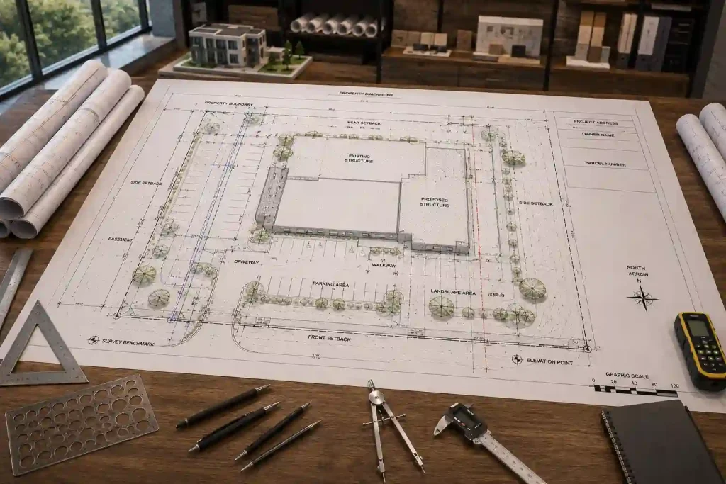
If you want to learn how to read a site plan, start by gathering accurate project information before the drawing is prepared. A complete and organized information package helps create a clear, scaled, and permit-ready site plan while reducing the chances of revisions or delays.
Before ordering or preparing your site plan, collect your property address, a brief description of the proposed work, rough measurements, and clear photos of the project area. If you have an existing property survey, plot plan, contractor sketch, or HOA aBefore you order or prepare your site plan, gather your property address, a brief description of the proposed work, rough measurements, and clear photos of the project area. Also, include any existing property survey, plot plan, contractor sketch, or HOA and zoning documents if you have them. Even if these documents are outdated or incomplete, they still provide valuable context and help create a more accurate site plan.
Understanding how to read a site plan also means knowing that the goal is not to produce a complicated architectural drawing. Instead, the objective is to provide the building department with a clear, accurate, and easy-to-read site plan that meets local permit requirements. A well-organized drawing with correct dimensions, simple labels, and project-specific details is easier for permit reviewers to understand and approve. By gathering the right information from the beginning, you can streamline the permit process and improve your chances of receiving approval without unnecessary delays
How to Read a Site Plan: Common Mistakes to Avoid
Learning how to read a site plan can help you avoid common mistakes that often lead to permit delays. Check property boundaries, setbacks, dimensions, building placement, easements, and labels carefully to ensure your site plan is complete and accurate before submission. Most permit delays happen due to avoidable errors such as:
- Using non-scaled sketches or screenshots
- Missing setback information
- Incorrect or outdated structures shown
- Ignoring easements or utility lines
- Submitting generic drawings instead of site-specific plans
- Mismatch between site plan and floor plan
Many applicants also face delays due to common site plan errors that cause permit rejection, especially missing setbacks or incorrect labels.
Site Plan vs Other Construction Drawings
A site plan is often confused with other architectural drawings.
- Site Plan → shows entire property layout
- Floor Plan → shows interior room layout
- Elevation Drawing → shows building exterior views
- Survey Plan → legal boundary measurement document
Each serves a different purpose, but all must align for permit approval.
Ready to Get Permit-Ready Site Plans?
If you want accurate, city-approved site plans without delays, professional drafting can save time and reduce rejection risks.
- Fast turnaround
- Permit-ready drawings
- reviewer-requested revisions within the original agreed scope
- Designed for local building departments
Get your project reviewed and prepared for approval with confidence and If you want accuracy without delays, our professional site plan drafting services ensure your drawings meet city requirements.
Frequently Asked Questions
What is a graphic scale on a site plan?
A graphic scale is a drawn bar that shows exactly how distance on the paper corresponds to real-world distance. Unlike a written scale (1″=20′), a graphic scale remains accurate even if the drawing is photocopied or enlarged.
How do I find the setback dimensions on a site plan?
Setback dimensions are shown as measurements between the structure and the property lines. Look for dimension lines (with arrows at each end) running from the edge of a structure to a property line, with the measurement labeled in feet.
What does a dashed line mean on a site plan?
Dashed lines typically indicate proposed (not yet built) structures, underground elements, or elements above the cut plane. Always check the drawing legend/key if one is provided.
What is the difference between a site plan and a plot plan?
The terms are interchangeable — both refer to the same type of overhead scaled drawing showing property layout. Some jurisdictions use one term consistently; others use them interchangeably.
What is a graphic scale on a site plan?
A graphic scale is a visual bar that shows real-world distance, even if the drawing is resized or printed differently.
How do I find setback measurements?
Look for labeled dimension lines between structures and property boundaries.
What does a dashed line mean?
It usually represents proposed structures, underground features, or easements depending on the legend.
Are site plans and plot plans the same?
Yes. Both terms refer to the same type of scaled property layout drawing.